DEFINITY Enterprise Communications Server Release 6
Installation and Test for Multi-Carrier Cabinets
555-230-112
Issue 5
May 1998
Install and Wire Telephones and Other Equipment
Page 5-73Add the Fiber Optic Cable
5
2. Determine which slot (1 or 2) will contain the new fiber optic circuit pack.
Remove the circuit pack or the blanking plate from this slot.
NOTE:
If a circuit pack is removed from the required slot, it must be installed
into a different slot in the cabinet. All translations associated with this
circuit pack must also be moved.
3. Remove the circuit pack or the blanking plate from the slot next to the slot
determined in step 2. Two consecutive open slots are required to install
the fiber optic adapter.
NOTE:
If a circuit pack was removed in step 3, it will be replaced into the
same slot, later in this section.
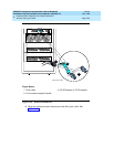
4. Install the new circuit pack.
5. Open the rear door.
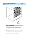
6. From the rear, remove the I/O cable connector associated with the slot that
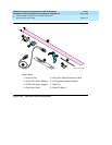
will contain the new fiber optic circuit pack. See Figure 5-30
.
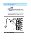
7. Using a supplied cable tie, secure the removed I/O connector to nearby
cabling. See Figure 5-31
.


