


DEFINITY Enterprise Communications Server Release 6
Installation and Test for Multi-Carrier Cabinets
555-230-112
Issue 5
May 1998
Install and Wire Telephones and Other Equipment
Page 5-40Emergency Transfer Units and Associated Telephones
5
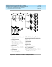
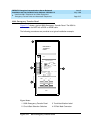
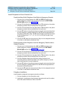
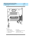
10. On the trunk identification label at the bottom of the panel, record the trunk
line, extension, and location for each circuit.
11. Attach a label identifying each voice terminal designated as an
emergency terminal. The labels are provided with the unit.
12. Check the system for normal operation:
— Set the test switch (switch 12) to NORMAL OPERATION.
— Ensure the power supply is providing -48 VDC at 80 mA maximum.
— The power LED should be ON.
— Verify there is dial tone on all emergency transfer sets.
If all of the above conditions are not met, replace the panel.
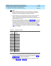
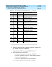
41 Y-BL TST4 Tip-Emergency Terminal 4
16 BL-Y RST5 Ring-Emergency Terminal 4
42 Y-O TTC5 Tip-PBX Trunk Circuit 5
17 O-Y RTC5 Ring-PBX Trunk Circuit 5
43 Y-G TTK5 Tip-CO Trunk Circuit 5
18 G-Y RTK5 Ring-CO Trunk Circuit 5
44 Y-BR TLC5 Tip-PBX Line Port 5
19 BR-Y RLC5 Ring-PBX Line Port 5
45 Y-S TST5 Tip-Emergency Terminal 5
20 S-Y RST5 Ring-Emergency Terminal 5
46 V-BL COM1 Common 1 Relay Contact
21 BL-V NO1 Normally Open 1 Contact
47 V-O NC2 Normally Closed 2 Contact
22 O-V NC1 Normally Closed 1 Contact
48 V-G COM2 Common 2 Relay Contact
23 G-V NO2 Normally Open 2 Contact
49 V-BR
24 BR-V
50 V-S GRD Ground From PBX
25 S-V -48PX -48V from Alm Panel
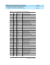
Table 5-14. Pin Assignments for 25-Pair Connector — Continued
Pin Color Designation Connector/Description
Continued on next page