


DEFINITY Enterprise Communications Server Release 6
Installation and Test for Multi-Carrier Cabinets
555-230-112
Issue 5
May 1998
Install Telecommunications Cabling
Page 2-19Cable Installation
2
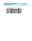
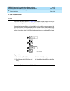
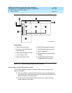
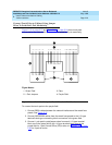
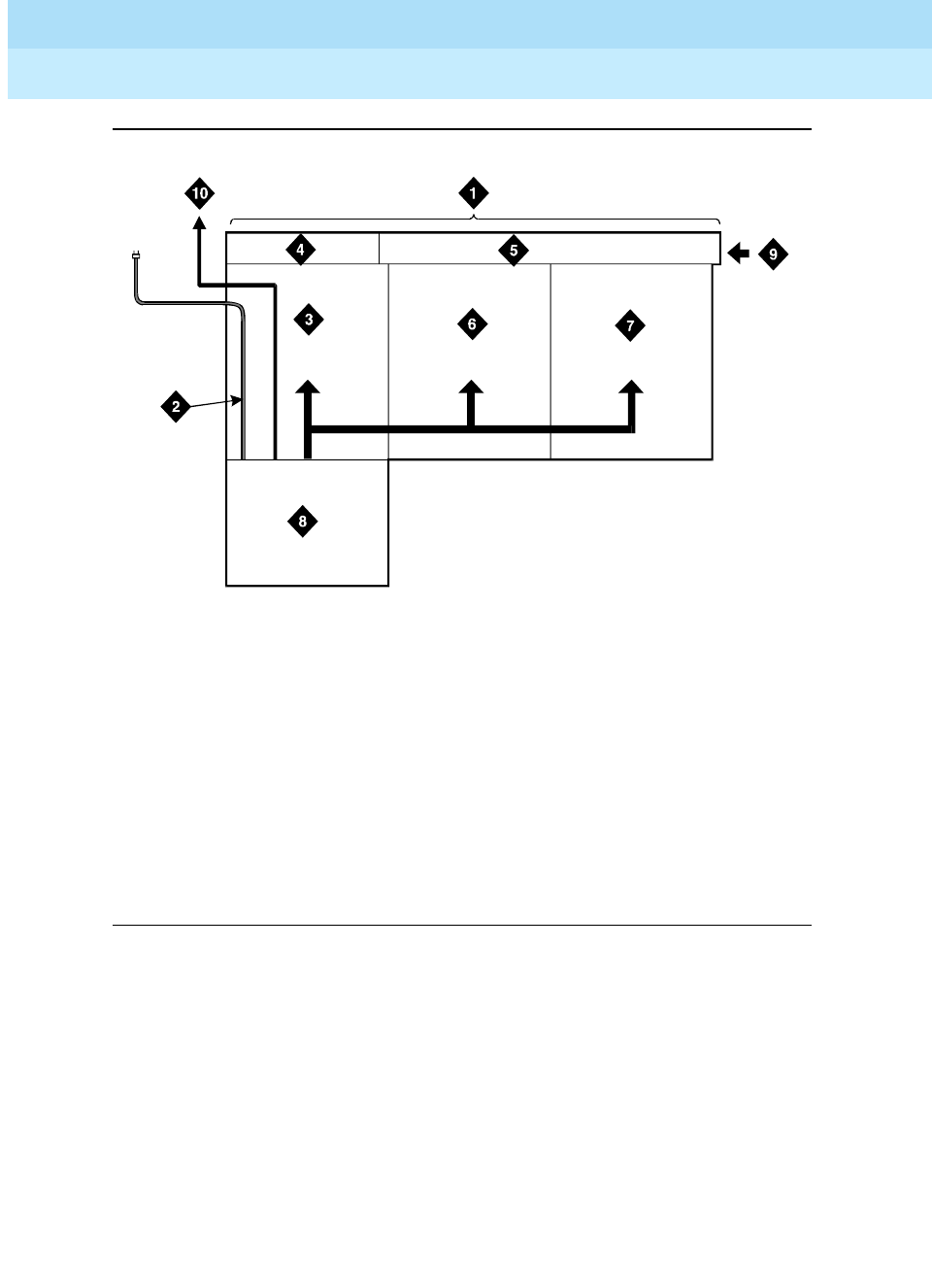
Figure 2-11. Cable Routing to Bottom Terminal Blocks
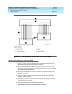
Route Cables to Main Distribution Frame
The following guidelines should be followed when routing cables from the
cabinet to the MDF.
■ Each port cable is connected at the cabinet and then routed along the
front trough of the cable slack manager to the connecting/terminal block
where the cable is to be terminated.
■ Enough slack must be left at the cabinet end of the cable to allow for
proper dressing of the cables.
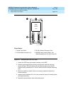
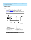
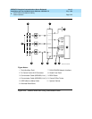
Figure Notes:
1. Main Distribution Frame
2. AC Power Cord (AC-Powered
Cabinets Only)
3. Cable Slack Manager Number 1
4. Trunk/Auxiliary Field
5. Station Distribution Field
6. Cable Slack Manager Number 2
7. Cable Slack Manager Number 3
8. System Cabinet(s)
9. Building Cables (Through Cable
Trough)
10. 10 AWG (#25) (6 mm
2
) Wire to
Coupled Bonding Conductor
r758432b MMR 052996