


DEFINITY Enterprise Communications Server Release 6
Installation and Test for Multi-Carrier Cabinets
555-230-112
Issue 5
May 1998
Install and Wire Telephones and Other Equipment
Page 5-491145B Power Supply
5
Install the Expanded Power Distribution Unit
A second power distribution unit can be installed to provide power to additional
8400-series and 8500-series terminals.
!
CAUTION:
Total power cannot exceed 200 Watts. The maximum ISDN terminal mixture
is twenty four 7500-series and twenty four 8500-series terminals.
The maximum DCP terminal mixture is twenty four 7400-series and twenty
four 8400-series or sixty four 8400-series terminals.
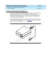
The following items are supplied with each expanded power distribution unit kit:
— One 1146B Power Distribution Unit (comcode 107250995)
— One “T” Cable (comcode 847529872)
— Two #8-32 x 1/2-inch Shoulder Screws
— One #8-32 x 1 inch Screw
— One Spacer Bracket (comcode 847554441)
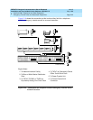
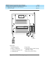
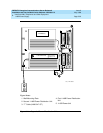
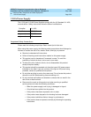
Refer to Figure 5-21
while installing the power distribution unit.
1. Set the spacer bracket onto the mounting plate and secure with the #8-32
x 1/2-inch shoulder screws. The spacer bracket is not shown in Figure
5-21 but is installed behind the top power distribution unit.
2. Slide the keyhole slots in the power distribution unit over the shoulder
screws.
3. Insert the #8-32 x 1 inch screw through the distribution unit, through the
spacer bracket, and into the plate. The mounting hole is located just
above the wire clip. Tighten the screw securely.
4. Set the battery back-up switch to the 1-32 (down) position.
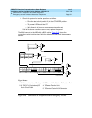
5. Power-down the 1145B unit as described on the label on the side of the
unit.
6. Remove the output power cable between the 1145B and the 1146B units.
The cable will not be reused.
7. Connect the P1 connector end of the “T” cable to the bottom power
distribution unit. Connect the P2 connector to the top distribution unit.
Connect the P3 connector to the 1145B.
8. Power-up the 1145B as described on the label on the side of the unit.