


Page 198 Epson Research and Development
Vancouver Design Center
S1D13708 Hardware Functional Specification
X39A-A-001-02 Issue Date: 02/03/07
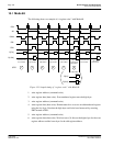
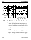
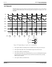
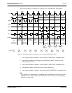
The following shows an example of a “memory read” for Mode 68 when the Memory
Access Select bit is enabled (REG[C6h] bit 0 = 1).
Figure 15-6 Sample timing of “register read” for Mode 68 when Memory Access Select Enabled
1. write register number of Memory Access Start register (REG[C4h]) (command write).
Note
No “data write” is required after a command write to the Memory Access Start register
(REG[C4h]). This step configures the S1D13708 for burst memory access beginning
with the next data read.
2. read Memory data (data read).
If the Memory Access Select bit (REG[C6h] bit 0 = 1), memory accesses are word ac-
cesses even if EBU is high (EBU is ignored and EBL is used to read both the upper
and lower bytes). The big/little endian setting is used to determine the data arrange-
ment for word accesses only.
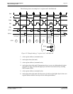
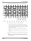
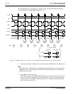
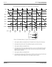
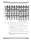
The S1D13708 indirect interface implements an auto increment function to allow
A0
CS#
EBL
R/W#
EBU
D[7:0]
D[15:8]
Little endian
DATA2DATA0 DATA8
DATA12
command write
MemoryAccessStart
data read data read data read data read
word access
DATA9
DATA n+1
DATA n
Big Endian
D[7:0]
D[15:8]
data read data read
data read
DATA4
DATA6
DATA10
DATA11
DATA n
DATA n+1
Little Endian
Data arrangement
word access
DATA1
DATA3 DATA5 DATA7
DATA13
word accessword access
word accessword access word access
Address +2
(word)
Address +2
(word)
Address +2
(word)
Address +2
(word)
Address +2
(word)
Address +2
(word)
1 2 2 2 2 22 2
STEP