


Epson Research and Development Page 71
Vancouver Design Center
Hardware Functional Specification S1D13708
Issue Date: 02/03/07 X39A-A-001-02
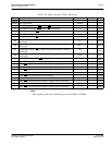
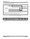
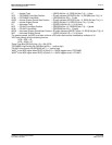
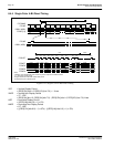
VT = Vertical Total = [(REG[19h] bits 1-0, REG[18h] bits 7-0) + 1] lines
VPS = FPFRAME Pulse Start Position = 0 lines, because [(REG[27h] bits 1-0, REG[26h] bits 7-0)] = 0
VPW = FPFRAME Pulse Width = [(REG[24h] bits 2-0) + 1] lines
VDPS = Vertical Display Period Start Position = 0 lines, because [(REG[1Fh] bits 1-0, REG[1Eh] bits 7-0)] = 0
VDP = Vertical Display Period = [(REG[1Dh] bits 1-0, REG[1Ch] bits 7-0) + 1] lines
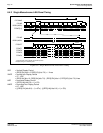
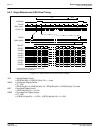
HT = Horizontal Total = [((REG[12h] bits 6-0) + 1) x 8] pixels
HPS = FPLINE Pulse Start Position = [(REG[23h] bits 1-0, REG[22h] bits 7-0) + 1] pixels
HPW = FPLINE Pulse Width = [(REG[20h] bits 6-0) + 1] pixels
HDPS = Horizontal Display Period Start Position= 22 pixels, because [(REG[17h] bits 1-0, REG[16h] bits 7-0)] = 0
HDP = Horizontal Display Period = [((REG[14h] bits 6-0) + 1) x 8] pixels
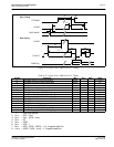
*For passive panels, the HDP must be a minimum of 32 pixels and must be increased by multiples of 16.
*HPS must comply with the following formula:
HPS > HDP + 22
HPS + HPW < HT
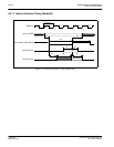
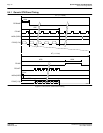
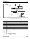
*Panel Type Bits (REG[10h] bits 1-0) = 00b (STN)
*FPFRAME Pulse Polarity Bit (REG[24h] bit 23) = 1 (active high)
*FPLINE Pulse Polarity Bit (REG[20h] bit 7) = 1 (active high)
*MOD
1
is the MOD signal when REG[11h] bits 5-0 = 0 (MOD toggles every FPFRAME)
*MOD
2
is the MOD signal when REG[11h] bits 5-0 = n (MOD toggles every n FPLINE)