


Epson Research and Development Page 9
Vancouver Design Center
Connecting to a Micro-Controller via the Indirect Interface S1D13708
Issue Date: 01/12/12 X39A-G-020-01
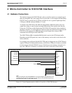
3 S1D13708 Host Bus Interface
The S1D13708 directly supports many microprocessor busses, of which two are Indirect
Interface modes, Mode 68 and Mode 80. Both modes can be used for micro-controllers
where IO lines are available for use as a bus to the S1D13708.
Actual bus cycles will typically be controlled by software unless the micro-controller
supports the Indirect Interface natively.
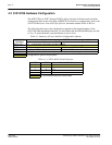
The Indirect Interface modes are selected by the S1D13708 based on the CNF[7:0] pin state
on the rising edge of RESET#. After RESET# is released, the bus interface signals assume
their selected configuration. For details on the S1D13708 configuration, please refer to
Section 4.2, “S1D13708 Hardware Configuration” on page 14.
The S1D13708 clock (CLKI) is taken from the micro-controller bus clock in synchronous
operation or from any other source for asynchronous bus operation. If the CLKI2 and
XTAL inputs are not used they should be tied to ground, as with all other unused inputs.
For more information on the Indirect Interface mode interface, please refer to the
S1D13708 Hardware Functional Specification, document number X39A-A-001-xx.
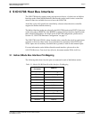
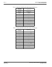
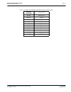
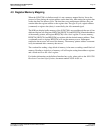
3.1 Indirect Mode Bus Interface Pin Mapping
The following table shows how the pins are connected in each of the Indirect modes.
Table 3-1: Mode 68 8-Bit Data Host Bus Interface Pin Mapping
S1D13708
Pin Names
Mode 68
AB[16:0] connect to V
ss
DB[15:8] connect to V
ss
DB[7:0] D[7:0]
CS# Chip Select
M/R# A0
CLKI BUSCLK
RD/WR# R/W#
RD# connect to V
ss
WE0# EBL
WAIT# not connected
RESET# RESET#