


Page 12 Epson Research and Development
Vancouver Design Center
S1D13708 Connecting to a Micro-Controller via the Indirect Interface
X39A-G-020-01 Issue Date: 01/12/12
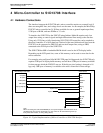
3.2 Host Bus Interface Signals
The S1D13708 Indirect Interface mode 68 and 80 host bus interface requires the following
signals from a micro-controller.
• CLKI is a clock input which is required by the S1D13708 Host Bus Interface as a source
for its internal bus and memory clocks. This clock is typically driven by the host CPU
system clock. CLKI for the S1D13708 Indirect Interface can also be asynchronous with
respect to the micro-controller bus clock, i.e. the clocks can be out of phase and/or
different speeds. The only consideration to take into account is the software routines that
control the bus cycles. The routines need to meet the bus interface timing requirements
according to the S1D13708 bus clock.
• The data bus, DB[15:0] or DB[7:0], must be connected to bi-directional pins of the
micro-controller lines.
• Chip Select (CS#) must be driven low when the S1D13708 is accessed by the micro-
controller.
• M/R# [A0 (command signal)] selects between the signals on the data bus as being a
register address or memory/register data.
• The RESET# (active low) input of the S1D13708 may be connected to the system
RESET#.
The next three signals only apply to Mode 68:
• WE0# (EBL, active low) is the low byte enable input for both read and write cycles.
This signal needs to be tied to a general purpose output line of the micro-controller.
• WE1# (EBH, active low) is the high byte enable input for both read and write cycles.
This signal needs to be tied to a general purpose output line of the micro-controller for a
16-bit data bus, or to ground for an 8-bit data bus.
• RD/WR# (R/W#, active low) must be driven high for read accesses and low for write
accesses. This signal needs to be tied to a general purpose output line of the micro-
controller.
Note
Mode 68 requires the S1D13708 BS# and RD# signal inputs be tied to V
SS
.
The next four signals only apply to Mode 80:
• RD/WR# (RDL#, active low) is the low byte enable for read cycles. This input signal
needs to be tied to a general purpose output line of the micro-controller.
• RD# (RDU#, active low) is the high byte enable for read cycles. This input signal needs
to be tied to a general purpose output line on the micro-controller for a 16-bit data bus,
or to ground for an 8-bit data bus.
• WE0# (WRL#, active low) is the low byte enable for write cycles. This input signal
needs to be tied to a general purpose output line of the micro-controller.
• WE1# (WRU#, active low) is the high byte enable for write cycles. This input signal
needs to be tied to a general purpose output line of the micro-controller for a 16-bit data
bus, or to ground for an 8-bit data bus.
Note
Mode 80 requires the S1D13708 BS# input signal be tied to V
DD
.