


Epson Research and Development Page 39
Vancouver Design Center
Hardware Functional Specification S1D13708
Issue Date: 02/03/07 X39A-A-001-02
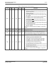
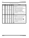
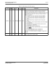
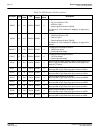
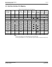
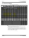
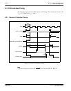
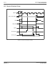
4.5 Host Bus Interface Pin Mapping
Note
1
A0 for these busses is not used internally by the S1D13708.
2
If the target MC68K bus is 32-bit, then these signals should be connected to D[31:16].
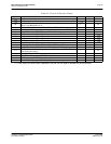
Table 4-9: Host Bus Interface Pin Mapping
S1D13708
Pin Name
Generic #1 Generic #2
Hitachi
SH-3 /SH-4
Motorola
MC68K #1
Motorola
MC68K #2
Motorola
REDCAP2
Motorola
MC68EZ328
/
MC68VZ328
DragonBall
Indirect
Interface
Mode 68
Indirect
Interface
Mode 80
AB[16:1] A[16:1] A[16:1] A[16:1] A[16:1] A[16:1] A[16:1] A[16:1] Connected to V
SS
AB0 A0
1
A0 A0
1
LDS# A0 A0
1
A0
1
Connected to V
SS
DB[15:0] D[15:0] D[15:0] D[15:0] D[15:0] D[15:0]
2
D[15:0] D[15:0] D[15:0] D[15:0]
CS# External Decode CSn# External Decode CSn
CSn External Decode
M/R# External Decode A0 A0
CLKI BUSCLK BUSCLK CKIO CLK CLK CLK CLKO BUSCLK BUSCLK
BS# Connected to IO V
DD
BS# AS# AS# Connected to IO V
DD
Connected
to V
SS
Connected
to IO V
DD
RD/WR# RD1#
Connected
to IO V
DD
RD/WR# R/W# R/W# R/W
Connected
to IO V
DD
R/W# RDL#
RD# RD0# RD# RD#
Connected
to IO V
DD
External
Decode
OE OE
Connected
to V
SS
RDU#
WE0# WE0# WE# WE0#
Connected
to IO V
DD
SIZ0 EB1 LWE EBL WRL#
WE1# WE1# BHE# WE1# UDS# DS# EB0 UWE EBU WRU#
WAIT# WAIT# WAIT#
WAIT#/
RDY#
DTACK# DSACK1# N/A DTACK
N/A N/A
RESET# RESET# RESET# RESET# RESET# RESET#
RESET_OUT
RESET RESET# RESET#