Epson Research and Development Page 89
Vancouver Design Center
Hardware Functional Specification S1D13708
Issue Date: 02/03/07 X39A-A-001-02
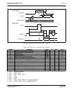
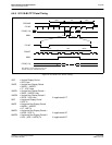
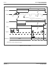
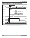
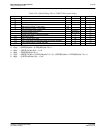
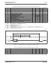
1. Ts = pixel clock period
2. t1typ = (REG[23h] bits 1-0, REG[22h] bits 7-0) + 1
3. t2typ = ((REG[12h] bits 6-0) + 1) x 8
4. t3typ = (REG[20h] bits 6-0) + 1
5. t7typ = ((REG[17h] bits 1-0, REG[16h] bits 7-0) + 5) - ((REG[23h] bits 1-0, REG[22h] bits 7-0) + 1)
6. t8typ = (((REG[14h] bits 6-0)) + 1) x 8
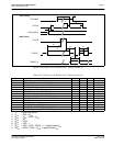
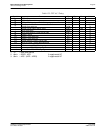
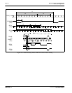
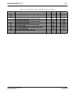
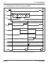
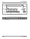
Table 6-26: 160x160 Sharp ‘Direct’ HR-TFT Horizontal Timing
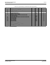
Symbol Parameter Min Typ Max Units
t1
FPLINE start position 13 (note 2) Ts (note 1)
t2
Horizontal total period 180 note 3 220 Ts
t3
FPLINE width 2 (note 4) Ts
t4
FPSHIFT period 1 Ts
t5 Data setup to FPSHIFT rising edge 0.5 Ts
t6 Data hold from FPSHIFT rising edge 0.5 Ts
t7
Horizontal display start position 5 (note 5) Ts
t8
Horizontal display period 160 (note 6) Ts
t9
FPLINE rising edge to GPIO3 rising edge 4 Ts
t10 GPIO3 pulse width 1 Ts
t11 GPIO1, GPIO0 pulse width 136 Ts
t12 GPIO1 rising edge (GPIO0 falling edge) to FPLINE rise edge 4 Ts
t13 GPIO2 toggle edge to FPLINE rise edge 10 Ts


