


45-29
User Guide for Cisco Security Manager 4.4
OL-28826-01
Chapter 45 Managing Firewall Devices
Configuring Firewall Device Interfaces
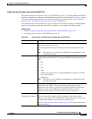
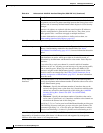
Configuring IPv6 Interfaces (ASA/FWSM)
When Interface, Subinterface, Redundant, or EtherChannel is the chosen Type in the Add Interface or
Edit Interface dialog box, the dialog box presents three tabbed panels of options: General, Advanced and
IPv6. The options provided by the IPv6 panel are described in this section.
Note These options are available only on ASA 7.0+ devices in routed mode; ASA 8.2+ devices in transparent
mode; and FWSM 3.1+ devices in routed mode.
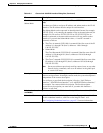
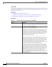
IPv4 Address Pool Enter or select the IPv4 Pool object that represents the pool of addresses to
use.
MAC Address Pool Enter or select the MAC Pool object that represents the pool of MAC
addresses to use.
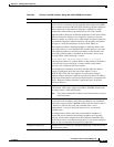
ASA Cluster (Layer 2); available on ASA 5580 and 5585 devices in cluster mode only.
Supported on EtherChannel interfaces for ASA clusters. Not supported on Management interface when
ASA cluster is in Transparent mode.
Span EtherChannel
across the ASA Cluster
Select to configure an EtherChannel that spans all ASAs in the cluster, and
provides load balancing as part of the EtherChannel operation.
Enable load balancing
between switch pairs in
VSS or vPC mode
(Optional) If you are connecting the ASA to two switches in a Virtual
Switching System (VSS) or Virtual Port Channel (vPC), then you should
enable load balancing by checking the Enable load balancing between
switch pairs in VSS or vPC mode check box. This feature ensures that the
physical link connections between the ASAs to the VSS (or vPC) pair are
balanced.
Member Interface
Configuration
Identifies the LACP mode for the interface and the Virtual Switching System
(VSS) or Virtual Port Channel (vPC) switch to which a given interface is
connected, 1 or 2.
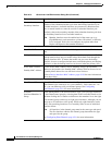
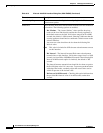
Advanced tab options specific to ASA 5505 devices (routed mode only)
Block Traffic To Restricts this VLAN interface from initiating contact with the VLAN chosen
here.
Backup Interface Choose a VLAN interface as a backup interface, for example, to an ISP. The
backup interface does not pass traffic unless the default route through the
primary interface fails. To ensure that traffic can pass over the backup
interface, be sure to configure default routes on both the primary and backup
interfaces so that the backup interface can be used when the primary fails.
Advanced tab options specific to FWSM 3.1+ devices
Bridge Group For an FWSM 3.1+ operating in transparent mode, this read-only field
indicates the Bridge group to which this interface is assigned. See Add/Edit
Bridge Group Dialog Box, page 45-41 for more information.
ASR Group To add this interface to an asymmetric routing group, enter the ASR group
number in this field. Stateful failover must be enabled for asymmetric
routing support to function properly between units in failover
configurations. Valid values for ASR group range from 1 to 32. See About
Asymmetric Routing Groups, page 45-5 for more information.
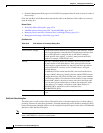
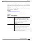
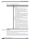
Table 45-4 Advanced tab: Add/Edit Interface Dialog Box (ASA/PIX 7.0+) (Continued)
Element Description