59-53
User Guide for Cisco Security Manager 4.4
OL-28826-01
Chapter 59 Configuring Router Interfaces
PVCs on Cisco IOS Routers
Note To edit a PVC, select it from the table, then click Edit. To remove a PVC, select it, then click
Delete.
Step 10 Repeat Step 2 through Step 9 to define additional PVCs.
Defining OAM Management on ATM PVCs
Security Manager enables you to configure the following F5 (VC level) Operation, Administration, and
Maintenance (OAM) cells for detecting PVC failures in a Cisco IOS router:
• Loopback cells
• Continuity Check (CC) cells
• Alarm Indication Signal (AIS) cells
• Remote Detection Indication (RDI) cells
You can enable and disable each of these cell types and define settings that determine how each cell type
affects the PVC when a failure is detected.
Before You Begin
• Select the ATM interface on which the PVC is defined.
• Define the general settings and the QoS settings of the PVC. See Defining ATM PVCs, page 59-50.
Related Topics
• Defining ATM PVCs, page 59-50
• PVCs on Cisco IOS Routers, page 59-46
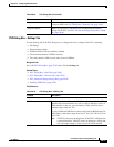
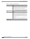
Step 1 In the PVC dialog box, click Advanced to display the PVC Advanced Settings dialog box. See
Table 59-27 on page 59-65 for a description of the fields in this dialog box.
Step 2 Enable OAM loopback cells on the selected PVC:
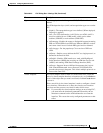
a. Click the OAM-PVC tab. See Table 59-29 on page 59-68 for a description of the fields on this tab.
b. Select the Enable OAM Management check box.
c. Define the frequency of loopback cell transmissions.
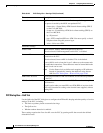
Step 3 (Optional) Enable segment CC cells on the PVC:
a. Under Segment Continuity Check, select Configure Continuity Check.
b. Choose whether the router should act as the sink, source, or both. This determines the direction in
which CC cells are sent.
c. Choose whether the PVC should remain up after segment or end-to-end failures are detected.
Note Select Deny Activation Requests to have the router reject CC activation requests received
from peers.


