59-9
User Guide for Cisco Security Manager 4.4
OL-28826-01
Chapter 59 Configuring Router Interfaces
Router Interfaces Page
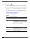
IP The method of IP address assignment for the interface:
• Static IP—Defines a static IP address and subnet mask for the
interface. Enter this information in the fields that appear below the
option.
Note You can define the mask using either dotted decimal (for
example, 255.255.255.255) or CIDR notation (/32). See
Contiguous and Discontiguous Network Masks for IPv4
Addresses, page 6-75.
• DHCP—The interface obtains its IP address dynamically from a
DHCP server.
• PPPoE—The router automatically negotiates its own registered IP
address from a central server (via PPP/IPCP). The following
interface types support PPPoE:
–
Async
–
Serial
–
High-Speed Serial Interface (HSSI)
–
Dialer
–
BRI, PRI (ISDN)
–
Virtual template
–
Multilink
• Unnumbered—The interface obtains its IP address from a different
interface on the device. Choose an interface from the Interface list.
This option can be used with point-to-point interfaces only.
Note Layer 2 interfaces do not support IP addresses. Deployment
fails if you define an IP address on a Layer 2 interface.
Layer Type The OSI layer at which the interface is defined:
• Unknown—The layer is unknown.
• Layer 2—The data link layer, which contains the protocols that
control the physical layer (Layer 1) and how data is framed before
being transmitted on the medium. Layer 2 is used for bridging and
switching. Layer 2 interfaces do not have IP addresses.
• Layer 3—The network layer, which is primarily responsible for the
routing of data in packets across logical internetwork paths. This
routing is accomplished through the use of IP addresses.
Negotiation Available on ASRs; applies to Fast Ethernet and Gigabit Ethernet
interfaces only.
Auto-negotiation detects the capabilities of remote devices and
negotiates the best possible performance between the two devices.
When Negotiation is enabled, the Duplex and Speed options are
disabled.
Table 59-3 Create Router Interface Dialog Box (Continued)
Element Description


