


65-6
User Guide for Cisco Security Manager 4.4
OL-28826-01
Chapter 65 Managing Cisco Catalyst Switches and Cisco 7600 Series Routers
Interfaces
• Interfaces/VLANs Page—Interfaces Tab, page 65-7
• Interfaces, page 65-5
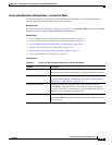
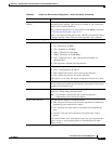
Step 1 (Device view) Select a Catalyst device, select Interfaces/VLANs from the Policy selector, then click the
Interfaces tab in the work area.
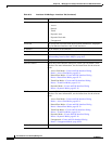
The Interfaces tab is displayed. For a description of the fields on this tab, see Interfaces/VLANs
Page—Interfaces Tab, page 65-7.
Step 2 Do one of the following:
• To define the attributes of a new interface, click Add Row.
• To edit the attributes of an interface, select it in the list, then click Edit Row.
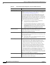
Step 3 (Optional) Deselect the Enable Interface check box if you want this interface to be in shutdown mode.
Step 4 From the Type list, select Interface or Subinterface:
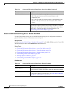
Step 5 (Interfaces only) Enter a name for the interface. You can click Select to open a dialog box that will help
you generate a standard name based on interface type and details about the interface’s location, such as
card, slot, and subinterface. For more information on using the dialog box to generate an interface name,
see Interface Auto Name Generator Dialog Box, page 59-12.
Step 6 (Interfaces only) Select an option from the Mode list to specify the port configuration type. The fields
in the dialog box vary according to your selection.
Step 7 (Subinterfaces only) Select the parent interface of the subinterface, then enter the ID number.
Step 8 Define or configure the settings for the type that you selected:
• Access Port—See Create and Edit Interface Dialog Boxes—Access Port Mode, page 65-9 for a
description of the fields.
• Routed Port—See Create and Edit Interface Dialog Boxes—Routed Port Mode, page 65-12 for a
description of the fields.
• Trunk Port—See Create and Edit Interface Dialog Boxes—Trunk Port Mode, page 65-14 for a
description of the fields.
• Dynamic Port—See Create and Edit Interface Dialog Boxes—Dynamic Mode, page 65-18 for a
description of the fields.
• Subinterface—See Create and Edit Interface Dialog Boxes—Subinterfaces, page 65-22 for a
description of the fields.
• Unsupported—See Create and Edit Interface Dialog Boxes—Unsupported Mode, page 65-24 for a
description of the fields.
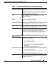
Step 9 From the Speed list, select an option to define the speed of the interface.
Step 10 If you defined a specific speed for the interface, and therefore the Duplex list is enabled, select a
duplexing option.
Step 11 In the MTU field, enter the maximum transmission unit value.
Step 12 Configure whether to use flow control on inbound (Receive) and outbound (Send) traffic.
Step 13 (Optional) Enter a description for the interface in the Description field.
Step 14 Click OK to save your definitions locally on the client and close the dialog box.